SEVT Mechanical Systems
I contributed to each of the mechanical systems during my time on the Solar Electric Vehicle Team. Below are some of the highlights.
Suspension
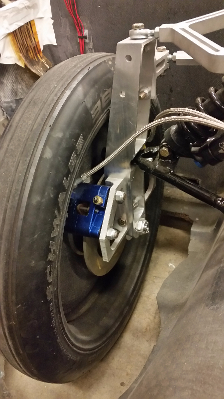
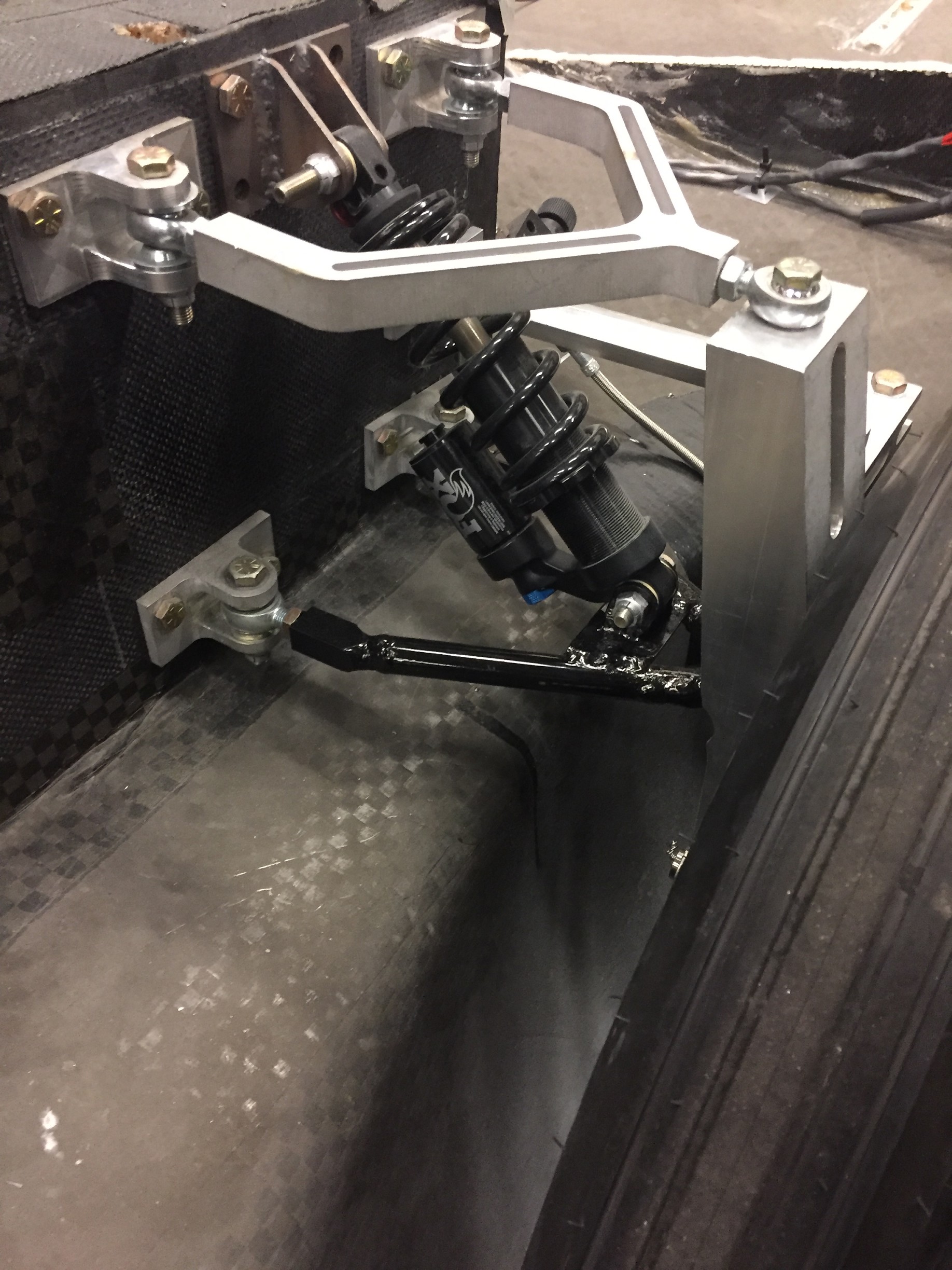 We have 4 independent suspension assemblies (with one driven and three undriven wheels), which is rated for a minimum of a 1G turn, 2G bump, and 1G brake force per the race regulations. Our suspension assemblies are composed of an aluminum upright, welded steel lower a-arms, aluminum upper a-arms (since it experiences much less of the forces), and a spring shock. The wheel assembly incorporates Michelin tires, carbon fiber rims, aluminum hubs that house two ball bearings, and heat-treated steel spindles.
I worked with the suspension CADs to create a 4-degree caster angle for front suspensions and edited the shock tabs to optimize the angle of the spring shock. I made edits to the previous hub and spindle CADs, created drawings for both, and worked with vendors to outsource the machining of them. I manufactured the upper a-arms with a combination of the waterjet and mill, and then installed steel threaded inserts where the rod ends would be inserted. I designed and waterjetted jigs to ensure that all suspension holes through the chassis would be in the correct locations.
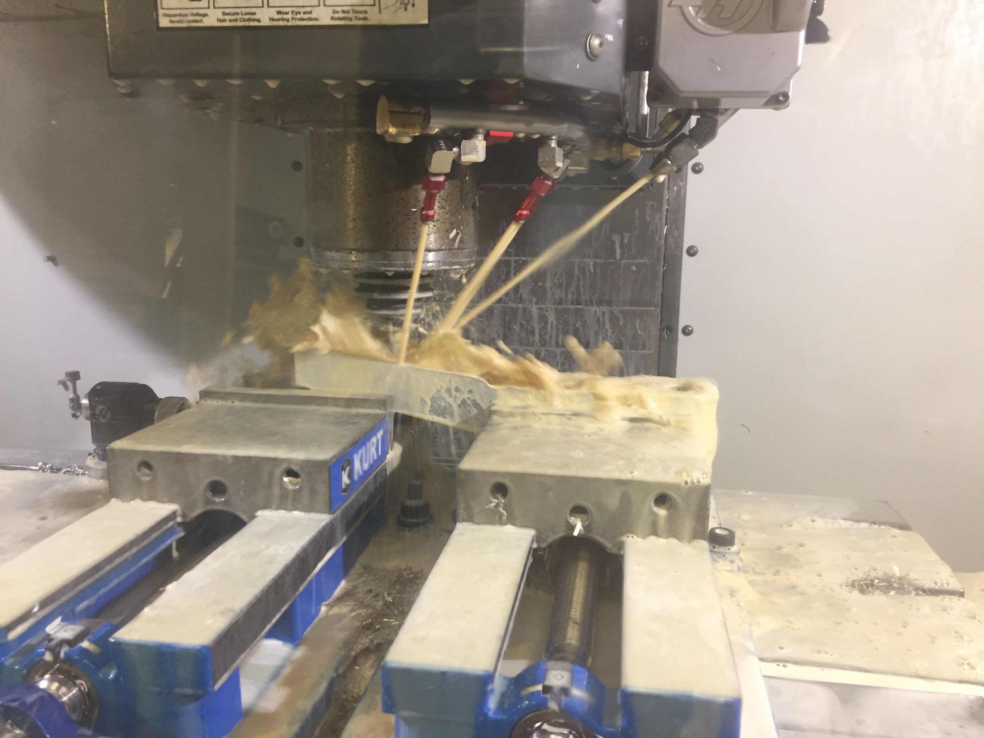
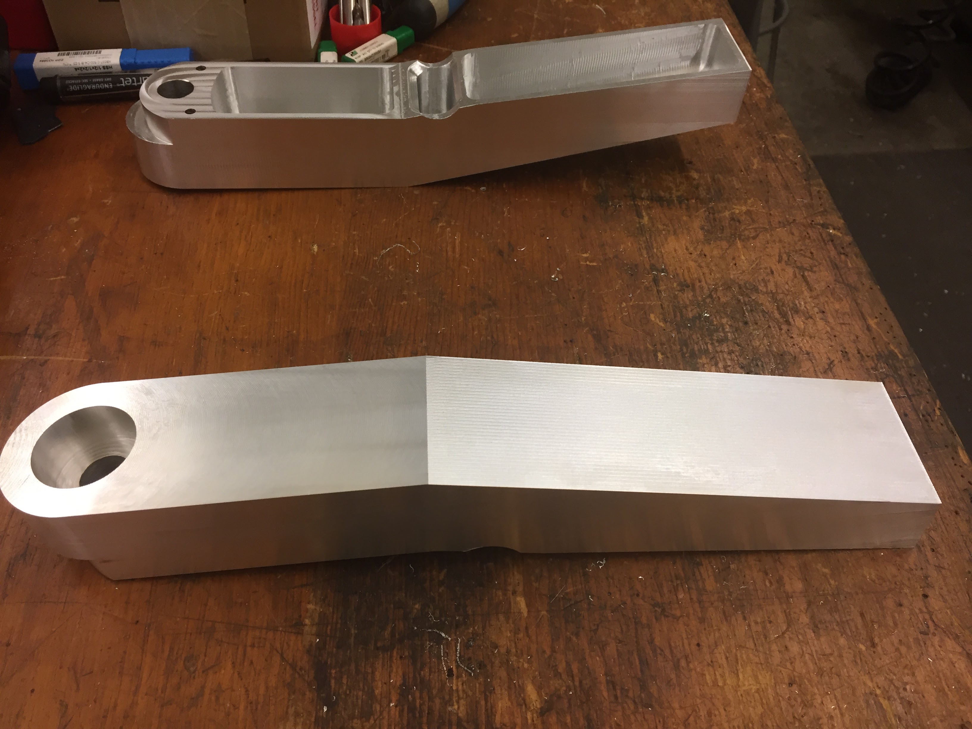
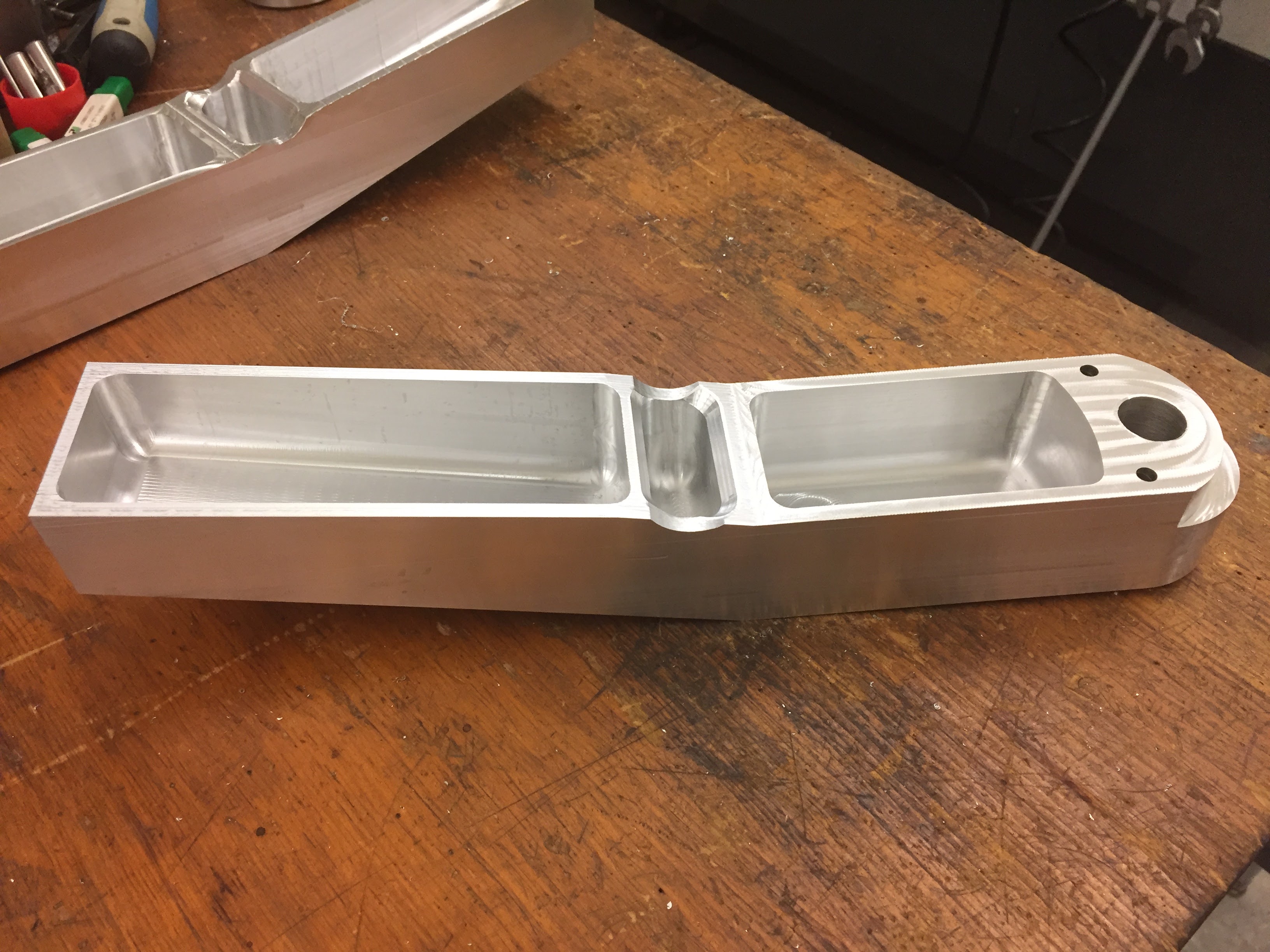
The upright is one of the central components of the suspension system, especially since it also connects to parts of steering and braking, and I was responsible for its manufacturing. I sourced the stock, wrote the toolpaths using HSMWorks to minimize the runtime and number of fixturings, and operated the HAAS to execute the toolpaths.
Brakes
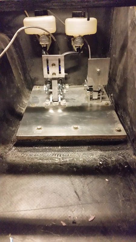
As a safety precaution, we have two hydraulically separate systems, both actuated by a single pedal. Our primary system connects to a caliper on every brake rotor, and a secondary brake system goes to additional calipers on the front wheels.
I designed the pedal assembly, which included designing the pedal, the attachments from the pedal to the master cylinders, as well as the mounts for both the pedal and the master cylinders.
I had to design the pedal such that the range of travel would displace enough fluid in the calipers to lock all wheels, and that the mechanical advantage of the pedal was high enough that the driver would be able to push the pedal through said range of travel.
Since the primary system requires more fluid displacement to lock the wheel than the secondary system, I also designed a balance bar for the pedal to allow greater travel of the primary master cylinder piston.
I also sourced all the plumbing components from brake lines and adapters to proportioning valves and hydraulic parking brakes.